Precision Center and Edge Finders: The Ultimate Workpiece Zero Calibration Guide
Before pulling the lever on a manual vertical mill or executing a line of high-velocity G-code on a 3-axis CNC machining center, establishing an absolute spatial relationship between the machine spindle axis and the raw material is critical. Any error in finding your workpiece coordinates will carry through the entire machining sequence, ruining concentricity, throwing off pocket alignments, and turning expensive raw stock into scrap. For industrial tool rooms, precision CNC workshops, automotive sub-assembly plants, and prototype engineering labs, using high-grade mechanical center and edge finders is the industry standard for fast, repeatable setup indexing.
Blue Fox Tool Mart carries a premium line of mechanical edge finders, double-ended center finders, wiggler sets, and acoustic-visual electronic positioning indicators. Engineered from hardened, ground alloy tool steel, these calibration instruments allow operators to find physical edges, internal bores, and center points down to the micron, maximizing workflow throughput while keeping part setups completely predictable.
1. The Engineering Mechanics of Spindle Axis Calibration
At its core, an edge finder acts as a mechanical bridge between the analog dimensions of raw stock and the digital or mechanical dials of your machine axis. Without dependable positioning tools, operators are forced to rely on visual estimation or risky "paper touch-off" methods that can easily mark delicate parts or chip expensive cutting tools.
Standard mechanical edge finders operate using a precision spring-loaded design split into two concentric sections: the upper mounting shank and the lower contact cylinder. When spun inside a collet at a steady 400 to 600 RPM, the lower tip wobbles deliberately out of alignment. As the table axis brings the raw material into contact with the spinning tip, the workpiece dampens the wobble until the contact cylinder spins perfectly straight. The exact moment the cylinder pushes past this alignment point, it "jumps" or slides sideways off-center. This distinct mechanical skip indicates that the spindle axis is exactly half the cylinder's diameter away from the workpiece edge.
Key Performance Attributes
- Hardened Steel Construction: Manufactured from EN31 or premium tool steel alloys hardened to HRC 55–60 to protect against surface wear, micro-dents, and corrosion from harsh cutting fluids.
- Micro-Finished Contact Profiles: Precision-ground surfaces finished to roundness tolerances within 0.002mm ensure highly repeatable readings across thousands of setup cycles.
- Internal Spring Calibration: Heavy-duty internal tension springs maintain consistent alignment tension, ensuring clean, sharp visual shifts without premature slipping or sticking.
2. Variations and Specialty Alignment Instruments
Different jobs call for different setup tools. Matching the right center or edge finder design to your specific part geometry cuts down on setup times and ensures solid measurement accuracy.
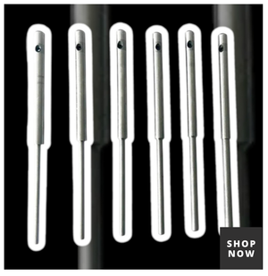
- Single-Ended Edge Finders: The go-to standard for everyday machine setups. These tools feature a uniform parallel shank, typically 3/8" or 1/2" diameter, paired with a single 0.200" or 10mm precision contact tip. They are ideal for straightforward X and Y axis alignment on clean plate stock, flat bar material, and square castings.
- Double-Ended Center and Edge Finders: Built for maximum versatility on the shop floor. These double-ended tools feature functional tips on both sides of the center shank, combining a standard 0.200" edge cylinder on one end with a 1/2" stepped cylinder or a pointed center finder on the other. This allows operators to flip between finding straight edges and locating central pockets without needing a second tool.
- Wiggler Sets & Pointed Center Finders: Designed to adapt to irregular layout work, scribed layout lines, and tight spaces. A wiggler set uses a universal chuck body that mounts a series of interchangeable ball-joint attachments. By running the wiggler tip against a finger or tool block while spinning, the machinist brings the needle to a perfect dead-center point. This point can then be aligned directly above scribed intersections or used to check runout inside small internal bore tapers.
3. Industrial Deployment Across Machining Environments
- CNC Machine Shops & Job Shops: Before running automated programs, operators use precision finders to double-check raw material positions against coordinate offsets. This extra step helps prevent tool holders from colliding with workholding setups like self-centering vises and ensures clean pocket cuts every time.
- Maintenance & Automotive Sub-Assembly Plant Operations: Technicians rebuilding commercial engines use wiggler sets and double-ended finders to align worn cylinders, map out bolt hole circles on custom adapters, and verify part lines on classic castings before re-machining.
- Educational Institutes and Research Labs: Schools and labs use mechanical edge finders to teach students foundational machining practices. Because these tools offer a clear visual shift at contact, they help students learn how to manage backlash and coordinate offsets safely on manual milling machines.
Setup Calibration Tool Comparison Matrix
Finder TypePrimary Diameter ProfileOptimal Spindle RPM RangePrimary Target GeometryRepeatability LimitSingle-Ended Edge Finder
0.200" / 10mm Cylinder
400 – 600 RPM
Flat edges, straight plate sides
±0.005 mm
Double-Ended Center Finder
0.200" Tip / 0.500" Body
400 – 600 RPM
Stepped edges, internal shoulders
±0.005 mm
Wiggler Point Attachment
Needle Profile Tip
800 – 1000 RPM
Scribed layout lines, punch marks
±0.012 mm
Electronic Visual Indicator
20mm / 0.750" Shank
0 RPM (Static)
Non-magnetic conductive alloys
±0.003 mm
Technical Maintenance Protocols for Metrology Tools
To keep your calibration instruments reading accurately over years of shop use, follow these standard care and maintenance procedures:
Cleaning and Storage Routines
- Clear Chips and Grit After Every Use: Always wipe down your edge finders with a clean microfiber cloth after use. Fine iron dust and abrasive grit can work their way into the spring seams, throwing off the tool's accuracy.
- Apply Light Rust Protection: Wipe a light film of metrology oil or low-viscosity rust-preventative lubricant over the ground steel bodies. Store the tools inside dedicated fitted cases to protect their micro-finished surfaces from accidental nicks and dents.
- Inspect the Internal Spring regularly: Check that the lower contact cylinder snaps back smoothly into position when pulled lightly. If the cylinder feels gummy or drags, clean it with an industrial solvent bath to remove dried oil residue.
Managing Spindle Runout Errors
- Verify Spindle Taper Cleanliness: Even a tiny speck of dust inside your machine's spindle or collet chuck can throw an edge finder off center. Always wipe out the spindle taper before mounting calibration tools.
- Compensate via 180-Degree Checking: If you suspect spindle runout, take your reading, rotate the edge finder 180 degrees inside the collet, and take a second reading. Splitting the difference between the two numbers helps cancel out minor machine alignment errors.
Critical Workshop Safety Guidelines
- Never Exceed Recommended Spindle Speeds: Keep spindle speeds between 400 and 600 RPM for mechanical edge finders. Running them past 1000 RPM can cause the internal spring to over-stretch, throwing the contact tip out of balance and turning it into a workshop safety hazard.
- Check Collet Grip Security: Make sure the tool's shank is fully gripped inside the collet. A loose edge finder can slide upward during contact, giving you inaccurate Z-axis readings and potentially damaging the tool face.
- Keep Your Hands Clear of Spinning Parts: Always watch for the visual shift or slide from a safe distance. Never touch a spinning tool body while attempting to locate a part edge.
Strategic Shop Integration: Live Collection Architecture
Keep your machine shop running smoothly by connecting with our primary equipment lines:
- Setup, Alignment & Metrology Gear: Find exact coordinate zeros using our Center and Edge Finders and Center Finders categories, and check final dimensions using Gauges and Protractors.
- Industrial Workholding Configurations: Secure raw material safely with heavy-duty Clamps and Vises, speed up multi-axis setups using Self-Centering Vises, and manage flat grinding operations with Precision Grinding Vises.
- High-End Production Cutting Gear: Equip your tool holders with long-lasting Tool Bits and Parting Blades, explore our full selection of shop gear on the Blue Fox Tool Mart Homepage, check our latest additions via New Arrivals, and find specialized production tools under Lathe Tools & Accessories.
- Specialized Maintenance Tools: Service commercial injection systems accurately using our industrial Nozzle Testers.
Manufacturing Industry Evolution: High-Authority Metrology Trends
As manufacturing moves toward automation and smart factories (Industry 4.0), workpiece alignment is evolving rapidly. While digital touch probes now handle complex, automated alignments on high-end five-axis CNC machines, mechanical edge and center finders remain vital tools in modern workshops.
Their strength lies in their simple, mechanical design. They don't require batteries, software updates, or complex electrical connections, making them immune to the electronic interference common on busy shop floors. For quick prototyping runs, manual machine setups, and secondary quality checks, these tools provide an affordable, deeply reliable way to guarantee absolute accuracy.
Frequently Asked Questions (FAQs)
- What is the primary operational difference between a single-ended and a double-ended edge finder? A single-ended edge finder features a single precision contact cylinder (typically 0.200" or 10mm in diameter) on one end of the tool shank, built exclusively for locating flat workpiece faces. A double-ended center and edge finder features a functional tip on both ends. This design typically pairs a standard edge cylinder on one side with a stepped tip or pointed wiggler on the other, allowing operators to switch between finding flat faces and centering internal bores without swapping tools.
- At what spindle speed (RPM) should I run a mechanical edge finder? For best results, run mechanical edge finders between 400 and 600 RPM. This speed range provides enough centrifugal force to swing the contact tip off-center while keeping enough spring tension for a clean, visible "jump" when it touches the part edge. Running the tool above 1000 RPM can over-stretch the internal spring, ruining its calibration and creating a safety hazard.
- Why does the contact tip of an edge finder "jump" or slide sideways when it touches a part? The jump occurs due to sudden friction balance changes between the spinning tool components. As the spinning tool approaches a part, the material dampens the tip's wobble, bringing it perfectly inline with the spindle axis for a brief moment. Moving the machine axis just a fraction past this point causes the edge friction to overcome the internal spring tension, making the tip snap out of center instantly.
- Can mechanical edge finders be used on non-magnetic materials like aluminum, brass, or plastics? Yes, mechanical edge finders work perfectly on non-magnetic materials like aluminum, brass, copper, and hard plastics. Because their alignment relies entirely on physical contact and edge friction rather than magnetic pull or electrical conductivity, they deliver reliable readings across all solid, machinable materials.
- How do you use a wiggler center finder to align a scribed layout line intersection? Mount the wiggler body securely in your collet and start the spindle at roughly 800 RPM. Gently hold a rule or tool block against the side of the spinning needle tip until it runs perfectly true without wobbling. From there, look down the spindle axis and move the machine table until the needle point sits exactly above your scribed layout lines.
- What should I do if my edge finder tip does not jump cleanly? A sticky tip is usually caused by fine metal chips, dried cutting fluid, or old oil trapped inside the spring seams. Remove the tool and clean it thoroughly in a solvent wash or degreasing bath. Dry it completely and apply a single drop of low-viscosity metrology oil to the joints. If the tool still drags, the internal spring may be stretched or damaged, meaning it's time for a replacement.
- How do I calculate my true zero coordinate after the edge finder jumps? When the edge finder jumps, your spindle center line is exactly half the contact tip's diameter away from the workpiece surface. For a standard 0.200" tip, you must move the machine axis another 0.100" toward the part to bring the true spindle center inline with the edge. Once moved, clear your digital readout (DRO) to lock in your true zero point.
- Why is it important to clean the machine spindle taper before mounting an alignment tool? Even a tiny speck of dust or dried oil inside your spindle taper or collet chuck can tilt the tool slightly out of line, creating spindle runout. This minor tilt throws off your measurements, giving you inaccurate readings. Always wipe your collet and spindle taper clean before mounting setup tools.
- Can I use an edge finder on a manual drill press? Yes, you can use an edge finder on a drill press for basic layout work, provided the drill press has a high-quality spindle with minimal side play. Mount the finder inside a drill chuck, set the speed to roughly 500 RPM, and use the table handles to find your edges before drilling.
- What is the benefit of a center finder with a stepped body diameter? A stepped body profile allows you to align the tool against high shoulders, deep pockets, or overlapping clamps that would block a standard straight shank. The stepped clearance lets the tip reach deep features safely, giving you accurate readings on complex parts.
- How can I check if my edge finder has a bent shank? Mount the tool in a high-quality collet and spin it slowly by hand while watching the shank with a dial indicator. Any variation on the indicator dial shows that the shank is bent or out-of-round, meaning it needs to be replaced to maintain accurate setups.
- What is the difference between a mechanical edge finder and an electronic touch probe? Mechanical finders rely on visual skips and physical edge friction, requiring manual operation at low spindle speeds. Electronic touch probes remain static and use an internal circuit that lights up or beeps the moment the tip touches a conductive part. Electronic probes are faster for CNC work, but mechanical finders are tougher, more affordable, and don't need batteries.
- How does temperature change affect precision metrology finders in a machine shop? Extreme temperature shifts can cause steel tool bodies to expand or contract slightly. For the best accuracy on close-tolerance jobs, store your setup tools in the same room as the machines. This lets the steel adapt to the shop floor temperature, preventing thermal expansion from altering your measurements.
- Why do wiggler sets include an interchangeable disc contact attachment? The flat disc attachment is specially designed for checking positions inside narrow slots, keyways, or internal grooves where a standard round cylinder or pointed needle tip cannot fit or read reliably.
- Should I run an edge finder dry or use cutting fluid during setup? Always use edge finders dry. Applying cutting fluid or heavy oils to the contact zone reduces the friction needed for a clean visual shift, which can cause the tip to slide early and give you inconsistent zero readings.
- What makes EN31 alloy steel a preferred material for high-end center finders? EN31 alloy steel offers exceptional wear resistance and structural toughness after heat treatment. It holds its dimensions perfectly over time and resists surface scratching from contact with rough metal parts, making it an excellent choice for high-precision shop tools.
- How do you find the center of a pre-drilled hole using a double-ended center finder? Bring the stepped or cylindrical tip down inside the hole, then gently move your X and Y axes until the tip touches the front, back, and sides evenly without dropping out of center. Note the DRO readings at each edge; the exact midpoint between those numbers marks the true center of the hole.
- What causes an edge finder to vibrate wildly when running? Wild vibrations usually mean the spindle speed is set too high or the tool shank is bent. Double-check your machine's speed settings and drop the RPM back down to the recommended 400–600 range to restore a smooth, controlled wobble.
- Can a pointed center finder be used to align parts on a lathe tailstock? Yes, you can chuck a pointed center finder into a tailstock chuck to align scribed center marks on a raw billet before supporting it with a live center or starting a turning sequence.
- How should I store multiple wiggler attachments to prevent losing them? Store your wiggler set components inside a fitted, padded case with clear slots for each attachment